Spring 2015
![]()
| ARDUINO CW decoder |
Spring 2015 |
|
NEW 05/18/2015:
I2C interface for LCD
display, a new DEMO shows that beacon OZ7IGY can
be decodet, inclusiv the first letter of the call sign:
https://www.youtube.com/watch?v=G8QZlvM6YpQ&feature=em-upload_owner
This small design runs fine and long for a 9-volt battery, if you do not necessarily need to have backlight on the display (do not mount R6, 12 Ohm), it uses a lot of power, and a new battery is worn out in an hour or so. However, it would last for a long time without backlighting, and even with the new connecting a speaker to morse the received signals, there is a long time decoding on just a 9 volt battery.
HERE UNDER, LAST UPDATED: 07/03/2015
OZ1JHM, Hjalmar has described a very simple and lightweight construction, to decode telegraphy. It can be seen at this address: http://skovholm.com/cwdecoder
Hjalmar has a page on YAHOO:
https://groups.yahoo.com/neo/groups/oz1jhm/conversations/messages
where discussing and talking about different problems that builders have run into (English).
Coincidentally, I had a ARDUINO UNO lying from an old experiment, and it was immediately cited,
wired up, and after half an hour, I was running with Hjalmar decoder.
Now... I do not mean that one should buy a ARDUINO UNO, and put it in a nice box, and connect the various components, such as a display and power supply, etc., so I designed a print on the basis of experience experiments with Hjalmar's decoder.
Watch a video of the experiment here: https://www.youtube.com/watch?feature=player_embedded&v=Fu7fJvNlhLY
After my views, Hjalmar's code clearly composed of several different pieces of programs.
Some of them then, too, improved, at least in relation to the eyes to look at the code.
I made a new decoder routinen.
Hjalmar had 57 "if" -statement in the decoder, one for each letter or number he
decode,
so I transformed it into a table lookup, and this will appear in the code, so there are now only 2 "for" -statement and 2 "if" -statement
left to decode the received letter or number.
I feel that the decoding has been improved a bit by this change.
It's not certain that this will be the last change in the decoder software, for it is
not difficult to take the CPU and put it in ARDUINO UNO, if it has to be reprogrammed.
When reading application note for ATmega328P, it was not difficult to identify ports from ARDUINO UNO and find the equivalent of the processor, and after an hour or so, the diagram looks like this:

Comment
:
The 6 -pin connector J1 used by the advanced ARDUINO programmer to program
the CPU directly into the structure.
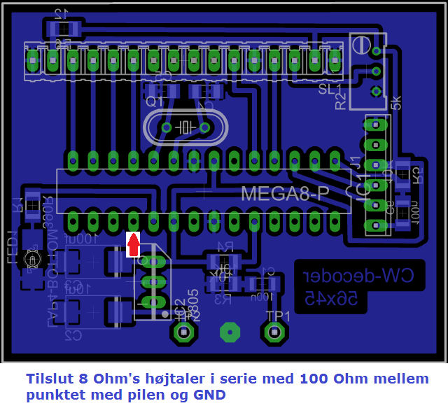
The sound of the speaker can be taken from pin 18 on the CPU in serie with MIN.
100 Ohm resistor. OBS:
Later ADDs...
Print
PCB :
After some troubles
with the local clus, EDR Fr.sund 's PCB manufacturing equipment, it proved possible to get made
an appropriate print,
with expanded service assistance from the Club President Joakim, OZ1DUG ,
and from this layout:
My capability to make print is NOT for produktion, so please make your ovn...
 |
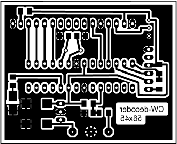
Here you can download a high resolution
PDF file with printdesign in the right size ..
|
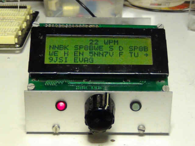
The final result should of course be seen, and therefore made in model "OPEN SAUCE" :)) as shown in the following pictures.
However,
it should be mentioned that there is added a switch on the small front panel to
the left of the red LED, which can turn on and off a lautspeaker generated by
the processor, as the decoding of signals. This causes the decoder as to act as
a kind of filter in relation to the sound coming out of the radio, which may be
weak or noisy.
What is heard in the small lautspeaker is a sound generated
only as a function of a decodet signal.
If the sound from lautspeaker is to high, then regulate the 100 Ohm resistor, but keep MIN. 100 Ohm.
Potentiometer at 10 K Ohm in serie with the signalwire, for regulating input to the processor. in mine version before the bandpass-filteret.
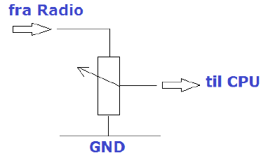 OBS: Potentiometer do NOT regulate the
speaker sound.
OBS: Potentiometer do NOT regulate the
speaker sound.
My experience with the decoder is, that it basically does what the author
promises. I have since decodet signals down to 3 S-degrees at 40 meterband.
For a while I even tried with a 4-circuit bandpass filter coupled between the
radio telephone socket and decoder, without seeing any significant improvement.
Impropvements could be done, maybee with a "Hy-Per-Mite"
- se the diagram here:
 Clich for full size...
Remember that a decoder is NOT better to read CW, than the way CW is attempted
to be read, is shipped. If the signal is weak, noisy or keyed with a paper clip,
even the best decoder, namely your ear, could have difficulty perceiving a message.
Do you want to play with CW (telegraphy) decoder, so this is a very nice little
project that will not cause you much anguish.
My version of the program can be DOWNLOADED
here ...
In top of program-text, you can change callsign or text as you wish... but..
look in the programtext to se option for decoding on all 4 display-lines.
Enjoy... de OZ6YM, Palle
I will answear all kind of questions to the project by e-mail: oz6ym (@)
planker.dk or via SKYPE: oz6ym_1
Do you have trouble getting it all to work, I will be happy to assist.
 |
 |
 |
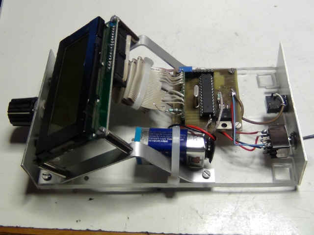
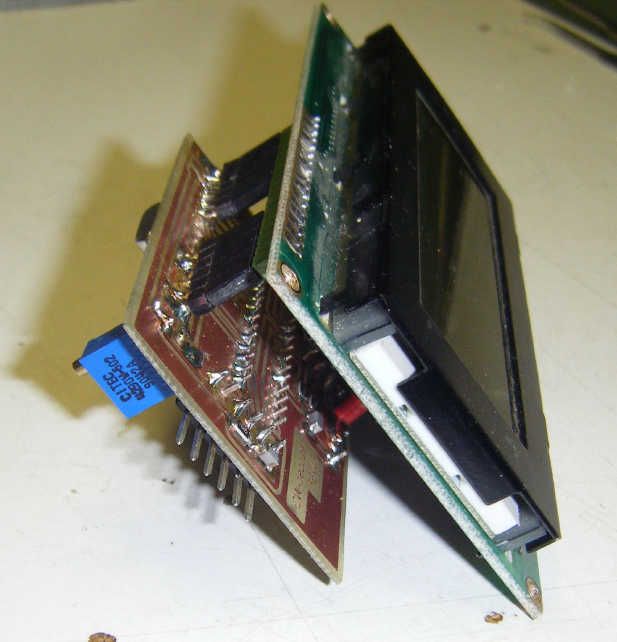 Here over, a version, where the print is mounted back on the display.
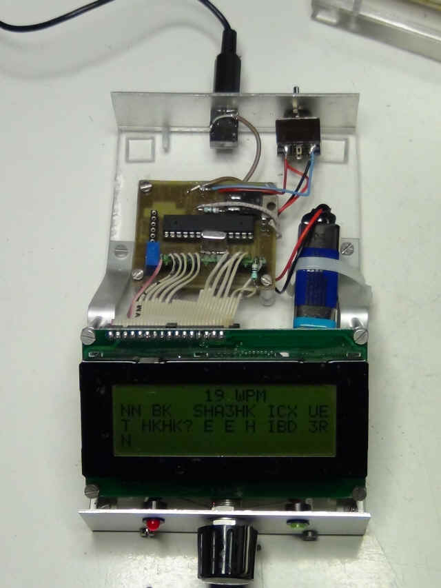
Here under is the final
eksperiment, with the added filter, and some added |
 |
 |
The backside of the construction shows power breaker and a 3,5 m.m. female Jack for signal input from the radio.